Sacked by the "downturn", an unemployed architect touring the country in a bus...


I used to live in New York City. I designed homes for the tycoons of Wall Street; Park Avenue, Scarsdale, Greenwich. It was great fun. And, after years of saving up for a down payment, I was just about to buy my own little place in Fleetwood, half an hour north of the city, when the economy fell apart. Architects are like canaries in a coal mine when the economy slows, and true to form, there were massive layoffs in firms all over the country. Devastation of the profession. So, I decided to try to find something else to do for a while. I bought a 23' school bus and I'm on the road to see if I can figure out what that might be.

Friday, October 22, 2010

Fabrication coming up...

Dan is drawing the computer model.  I meet with Mike Wednesday at 10 to see if his firm can make my parts.
Everyone has sent me such encouraging e-mails, it's really wonderful.  Special thanks to folks here in the shop for advice and help, with very special thanks and well wishes to Andrew Isley, who is recovering from heart surgery.  Also huge thanks to John and Mary Kathrine for their unbelievably generous hospitality and support.

Wednesday, October 20, 2010

First pic..

I shot this this morning so I can have something to show to talk with people.  I'll find a home or a theater with a grand piano for the background and set up more carefully lighted marketing photos.  But meanwhile, I'm excited to talk to all the people I've met up to this point, and to start looking for galleries and outlets.  I need to talk to the CNC fabricator, of course.  And then a few of the people I met up in Fort Bragg, including Dan Heman, a terrific sculptor and gallery owner.  Also, Bruce Mitchell, the well established sculptor Sandy and I met on Point Reyes.  Maybe he'll have suggestions for me.  And the woodworkers I met at College of the Redwoods...  Oh, John Castl used to live in SF, I wonder what he's up to these days...

I called the furniture fabricator today, and the CNC computer modeler.  I also drew up a few ideas for variations.  So much to do!

Tuesday, October 19, 2010

Done!

Pictures coming..

Friday, October 15, 2010

Making Glides

I made glides for the bottoms of the legs.  I used a black plastic cutting board for material, a very hard, layered plastic.  I built a platform to clamp to the legs to support a trim router which I used to cut the plastic to fit the legs.  Click here for the Flickr pics.

Tomorrow, when the shop is relatively empty, I will take the chair into the relatively dust free bathroom and apply the final finish coat of polyurethane.

Sunday, I will sit down. :-)

Thursday, October 14, 2010

Hi to M.I.T...

Hi Fab Lab!  Keep up the amazing work, and thanks for looking at my pursuits :-)

Tuesday, October 12, 2010

No such thing as "The Bottom"

A project like this demands attention to the bottom details.  To fasten the seat, I first got little zinc coated steel L brackets which would be screwed to the seat and the rails.  But the color doesn't match the brass cross ties.  I thought finding brass parts would be a real pain so I resolved to paint the zinc brackets and screws black.  However, at the hardware store today, to my surprise, I found brass L brackets and brass oval head screws, and nicely dimpled brass finish washers.  I also found brass shelf pins which I thought might work.  I bought 4 L's and 4 shelf pins, a box of the screws, and 8 washers.  I ended up using the shelf pins which worked very elegantly.  Between the frame and the seat, I had planned to lay in a felt weather strip.  Previously, I had only been able to find a foam rubber strip, which I bought, but today I spotted an old timey looking felt strip and I snatched it up.  It's been like that on much of this project, buying multiple choices of materials, and then finding the perfect thing later still.  Oh, well, that's product development biz. 

I installed dowels to mount the back rest and arm rests, then sanded all the Zebra wood parts with successively fine sandpaper up 400 grit.  I made some stands for the parts and applied a first coat of polyurethane.  Tomorrow, I will install the Zebra wood parts, do a final sanding on everything and be ready for a final coat of satin polyurethane.  Click here for the pics :-)

Monday, October 11, 2010

Attaching the Back Rest

I used the plywood back rest from the mock up to make a dowel hole drilling jig for the final pieces.  Click here for pics.

Testing the Back Joint and Geometry

Last night I made a simulation of the back support bottom mortise and tenon joint so I could test it.  This morning I loaded it.  Seems adequate :-)

Today, I made the connection for the back rest cross bar and test assembled the seat and backrest for a trial sit.  It felt very good, but I decided to trim the mating surface of the back support bottom joint, to raise the angle to be slightly more upright, about half an inch forward, which required just an eighth of an inch trim at the joint.  This is done now, including tweaking the pre-tensioning lag bolt at this support's weak spot.  Nothing left but to install the Zebra wood parts and apply final finish.

Click here  for the Flickr pics.

Saturday, October 9, 2010

Hi Hart Howerton

Hi BR, JM, RR, CP, and anyone else looking in from time to time :-)

Hope all is well.  I do miss NYC and HH from time to time.  But California is great, so eat your Harts out, lol.

Cheers

Gluing up

Click here for a Flickr show.  It's getting exciting :-)

Thursday, October 7, 2010

Staining

Tomorrow, I glue.

Ready to go,... wait, ONE MORE TEST!

Last night, I finished sanding all my wood parts to 400 grit.  I am ready to apply finish.

I went to sleep knowing that I can not make this any better.

But I woke at about 6, with a start; will the arms and back really work???   These are single pieces of wood sticking up, doing the work normally done by at least two vertical pieces on every chair I have ever seen.  I have a good sense of the strength of materials, but the little nub I was able to snap off so easily the other day, made me very nervous about the brittleness of this wood.  As I dressed (in my truck outside the shop, where I have been staying most nights, with visits to my friends John and MK  every few days) I already started contemplating a test of the arm and how I might redesign it if it proved inadequate.  I imagined a connection tieing the arm to the back support... but ugh, I don't want to have to do this.

Now in the shop, I found the old arm I had made when I started making the pieces, and secured it in the vise in a position where I could subject the weakest section to the greatest leverage.  I leaned lightly and shook the upright arm.  Then I threw my weight into it, not with all my strength as in a football tackle, but a good sturdy body thunk, well more than anything I can imagine might happen in the chair's daily use.  It held, much to my relief.  Ok, then I replicated the two small "finger" buttresses that will be on the final piece, and I joined them to the top of the arm, and then attached my plywood mock-up armrest using a biscuit joiner and glue, as I will on the final piece.  After just an hour of clamping time, I could not stand to wait any longer, so I put the arm back in the vice, and loaded the arm rest with my toolbox, which has become my default testing weight.  Again to my relief, it held.  And the backrest?  You may remember I have already installed a bolt through the weak point, so I'm pretty confident in that member.

Only a man who cares has doubt.  (proverb)

Will my mortise and tenon joints attaching the arms and back be sufficient?  Am I using the best glue, the yellow woodworking glue?  Should I use Epoxy, which is better able to fill voids as I have around my not so perfect m&t joinery?  Or the new polyurethane glues, like Gorilla Glue, which can expand to fill voids?  Each of these have problems, too; the epoxy is runny and messy and very hard to clean off if it gets on an exposed surface, and the polyurethane glues lose strength where they have room to expand, and the squeeze out from the expansion can make a mess too.  I looked over my joints again.  They're not so bad.  One could use a touch up.  I think I'll do that and stay the course with the old reliable yellow glue.

On to pre-finishing and prep for glue up.

Tuesday, October 5, 2010

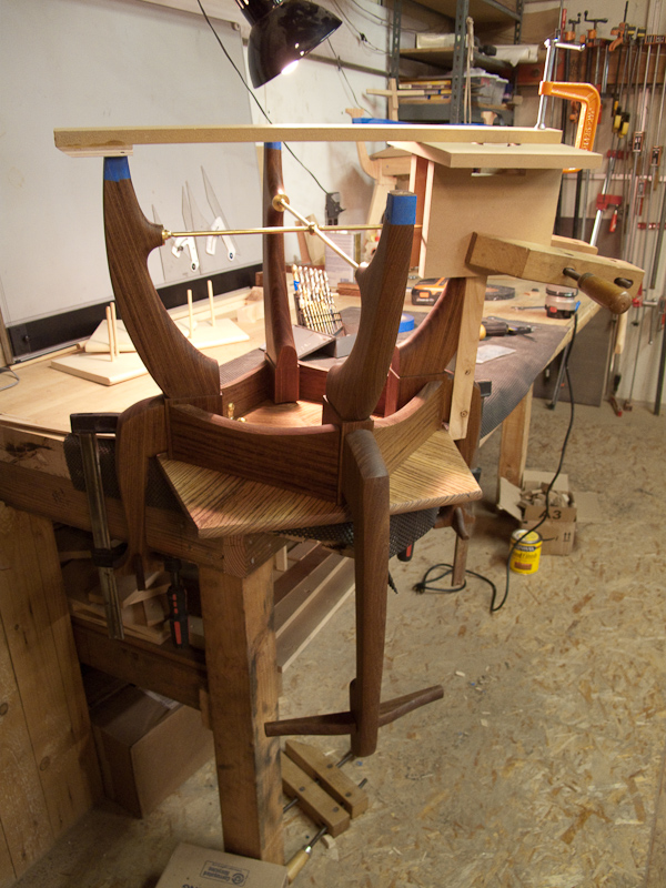
Installing the Cross Ties and a Partial Assembly

Today I assembled the bottom half of the chair to test fit the cross ties.  Click here for a Flickr show.  There is a sketch of the anchoring of the tie deep into the leg and a sequence of photos showing the execution.  I shaped the tip of a large screwdriver to accurately seat a brass insert deep inside the hole, at the middle level of three concentrically drilled diameters, the smallest of which is at the bottom and allows the threaded rod to over run when it is inserted.  The smallest diameter also provides a shoulder against which the brass insert stops.  The middle diameter is sized for the insert to screw into, and the upper largest diameter allows clearance for the insert to drop down to the beginning of the middle diameter, and also provides clearance for the screw driver.

There are also several photos of the bottom half of the chair assembled to test fit the cross ties.  (You may notice little pieces of wood in the middles of the arches that resemble keystones.  They are simply there to protect what will be smooth arches from being marred by the clamps.)  This is the first time I have seen this much together, and is the first confirmation that all of my geometry works and that all of my joinery and metal connections are correct.  Whew! I think about 400 hours have gone into this project (including all the figuring out of things, building jigs, testing, creating mock-ups, remaking parts, and a lot of research and self teaching of general woodworking techniques.)  Still, I am relieved that it all worked and I am now, for the first time, confident to proceed to glue up the chair!

By the way, I think it looks amazing.

Monday, October 4, 2010

Sunday, October 3, 2010

Making the Brass Cross Ties...

Click here for some photos of the fabrication of the brass knuckle for the center of the cross ties between the legs.  Also, a test of the strength of a mock up of the wood nub, to which the cross ties will attach.  The nub held fine with the weight of my tool box, even when I bounced it up and down.  But, when I applied a very small bending force to the nub, it snapped right off.  I am sure this is a property of the Afromosia, and will not be a problem with other wood species.  To complete this first chair, however, I decided to run the rods deep into meat of the leg, rather than simply into the protruding nubs.  The last photo shows the ball with one rod fitted and a terminus at the opposite end.  This terminus is too elaborate, and I will replace the knurled nut with an acorn nut, with a 1/4" hole drilled through it's crown to allow the rod to pass through.  The nut will retain the large, thick brash washer at the end, finishing the round end of the wood nub.  The edgers of the washer and the nub will be sanded together for a perfect fit.  A fine point on the ball is that in order to assemble the cross between the legs, I have made one hole in each direction with a reverse thread, and a mating thread on the end of the rod it receives.  This will allow me to twist the rod with one revers thread to shorten the length of the whole assembly, so that I can get it between the rigid legs, and then twist the rod the other way to lengthen it again, and position the ball correctly in space, before backing the apposing rod into it's normally threaded hole.

Friday, October 1, 2010

I love Berkely..

I asked a shopmate metalworker, Steven, how I could blacken and tarnish my brass parts.  He said "Why don't you throw them in this bucket? They'll blacken in a few hours."  I'd found on the internet 4 oz bottles for $9 ea. from hobby suppliers, and Steven had a whole Rubbermaid vat of the brew.